AQLARP
![]()
Welcome to the AQLARP documentation. This documentation is built with mdBook
AQLARP stands for Affordable Quadruped Learning And Research Platform.
AQLARP is licensed under the MIT license.
AQLARP was created as my final project for high school.
🚨 This documentation might be incomplete
It is advisable to have a basic understanding of the parts of the robot to effectively address encountered issues. If you need help, feel free to open an issue on AQLARP's GitHub. However there is no guarantee that I will be able to help you.
Design Principles
AQLARP stands for Affordable Quadruped Learning And Research Platform. These are the principles AQLARP is based on.
Platform
This is the most important principle for AQLARP. AQLARP should be a solid, extendable platform, which you can use as a starting point to build on and create your own amazing projects. Here are some of the design decisions to make AQLARP a platform:
- Extendibility: the top, front and back are easily replaceable with your own components that suit the needs of what you are trying to create.
- Interoperability: AQLARP makes use of ROS2 so you can easily write your own code, in any programming language you chose, that can effortlessly interact with other parts of AQLARP's codebase.
- Well Documented: AQLARP has good documentation to learn about AQLARP and how to extend it. Additionally AQLARP's code has clear comments to help you understand it.
Affordable
AQLARP is relatively affordable. The parts chosen are a balance of price and how suitable they are to build a platform. Affordability, however, comes second to making AQLARP a stable and extendable platform.
Learning
AQLARP can be used as a learning tool. To aid in this, AQLARP is well documented and extendable. Additionally AQLARP uses ROS2 which is commonly used in the robotics industry and is a valuable skill to learn.
Research
AQLARP is extendable and it is easy to add extra sensors to measure the influence of a variety of factors. Additionally AQLARP is open source so you can change anything you want to aid in your research.
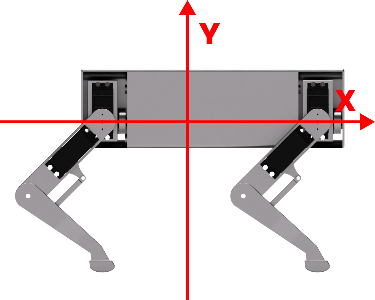
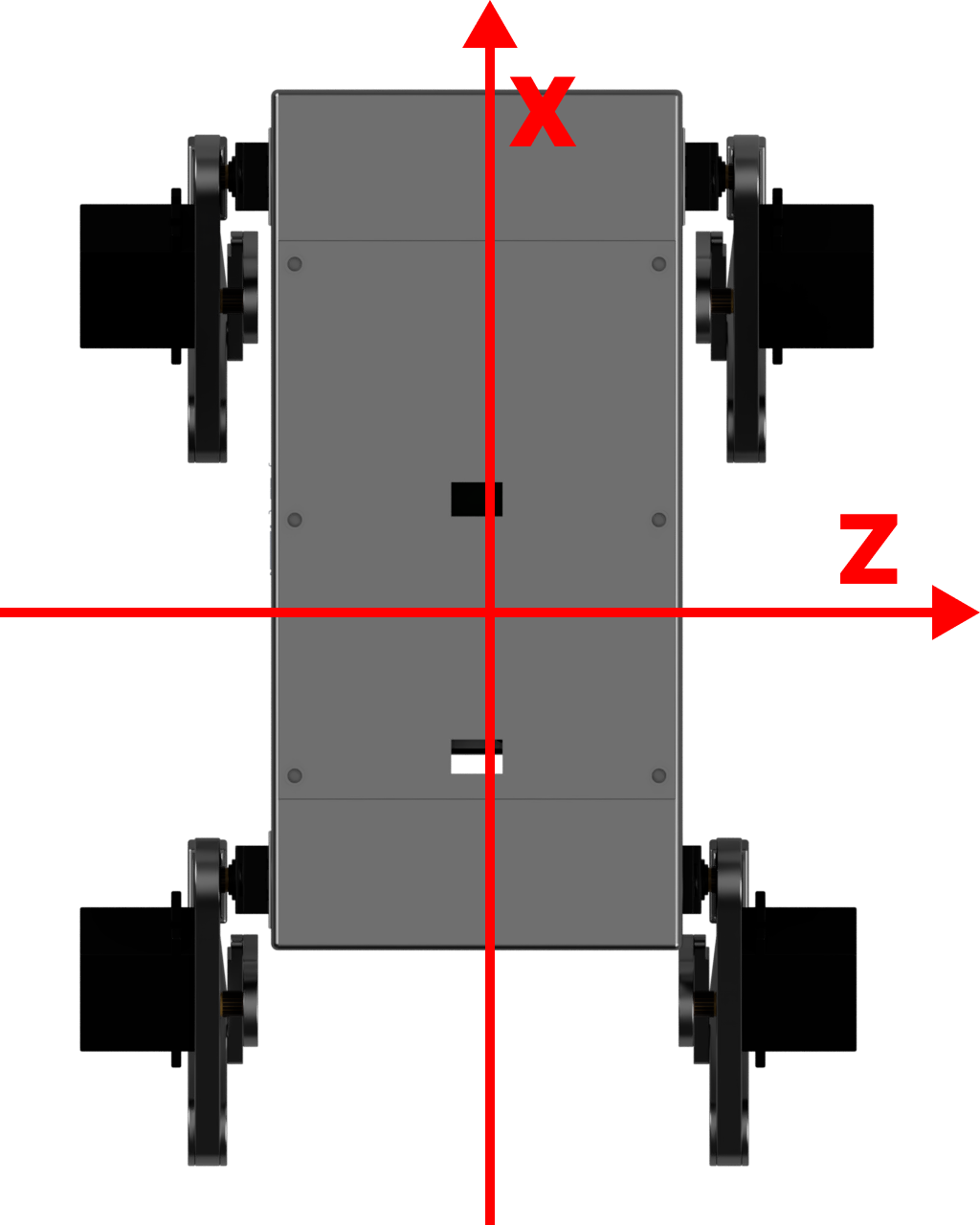
Defining AQLARP's coordinate system
Knowing AQLARP's coordinate system is import so you know what setting each axis will do. Here are the definitions for it:
- X-axis:
- Increasing the value will make AQLARP move to the front
- Decreasing the value will make AQLARP move to the back
- Y-axis:
- Increasing the value will make AQLARP go up
- Decreasing the value will make AQLARP go down
- Z-axis:
- Increasing the value will make AQLARP go to the right
- Decreasing the value will make AQLARP go to the left
The origin of these axis is where the leg is connected to the top joint, this is a per leg coordinate system.
Below are some images to clarify what axis does what.
Required Materials
AQLARP's bill of materials is available here. (download)
I would encourage you to look around and see if you can find parts for cheaper since these prices will change with time and depending on your area they may also vary.
Additionally you will have to have the following tools:
- Screw driver for the type of screws you choose
- Soldering iron
- 3D printer
Raspberry Pi setup
During the build process, it will be required to set the servos to 90 degrees at some points. To do this the raspberry pi should be set up and connected to the servo controller, which is what we will be doing here.
Installing Ubuntu
Firstly, install the Raspberry Pi Imager from their website. This is what we will be using to flash the Ubuntu image to a micro SD card.
After installing the imager open it up and select the appropriate Raspberry Pi device, if you are using the same parts this will be a Raspberry Pi 4. Then Click Choose OS and scroll down to Other general-purpose OS and click it. Then select Ubuntu and choose any 64-bit version. I would recommend using the latest LTS version (22.04.4 LTS at the time of writing). If you plan on ever connecting a display, choose the desktop version, otherwise the server version will be fine. Make sure to select a 64-bit version.
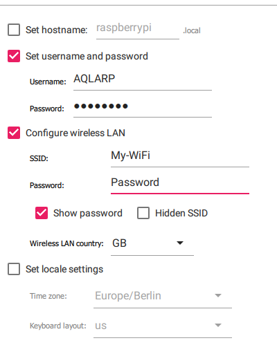
Now you have to specify some settings, to do this press Ctrl + Shift + X. Check the Checkbox Set username and password. For username you can set what you want, but the rest of this documentation will be based in the username AQLARP. Then choose a password you can easily remember, as we will need this later. Next, check the checkbox Configure wireless LAN, set SSID to the name of your WiFi network and enter the password in the password field.
Then click save, select your micro SD card with the storage button and click next to start flashing the image to the SD card. After this is done put the micro SD card in the raspberry pi and power it using the USB C port.
Connecting to the raspberry pi
Next you will have to find the IP of your Raspberry Pi. If you have access to the router you can log in to it's dashboard and find the IP as such. If you don't have access to the router finding the IP will be significantly harder and you will have to use a tool like nmap to find the IP. Make sure you can access other devices (like the Raspberry Pi) on your network. Some school or work networks might block this. If you cannot access other devices on your network, I would recommend using a cheap travel router. As an added bonus of this you will be able to easily view the Raspberry Pi's IP in the router's dashboard.
Once you have the IP you can connect using ssh. To do this open a terminal (search cmd in Windows and open it) then execute the following command:
$ ssh AQLARP@<Raspberry Pi Ip>
If you chose a different username than AQLARP, put it in the command instead of AQLARP. It will then ask you to input the password you chose when setting it up. If you can't immediately connect to the Raspberry Pi, be patient since it can take a few minutes for the Raspberry Pi to boot up.
Clone the Github Repo
Next you will have to clone the GitHub repo, since this contains all of AQLARP's code. To do this run:
$ git clone https://github.com/DeDiamondPro/AQLARP.git
Install dependencies
To use the scripts, some basic dependencies have to be installed. To do this run the following commands
$ sudo apt update
$ supt apt install -y python3 python3-pip i2c-tools
$ python3 -m pip install adafruit-circuitpython-servokit rpi.gpio
Connecting the servo driver
To connect to the servo driver, you can check the wiring image below.
The loopback from V+ to V+ might not be required if it is attached correctly, but it was required for me.
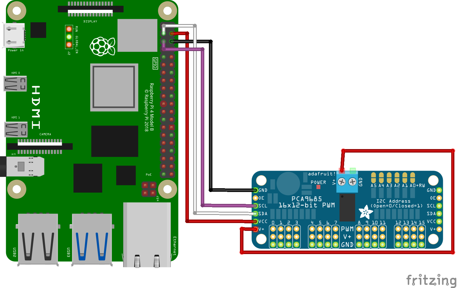 Connect V+ and GND (the socket version) to a power supply of 5-7V. This can be the battery and a voltage regulator if you wish.
Now to check if the controller is connected correctly, run the following command.
$ i2cdetect -y 1
You should see it show up with the address 0x40
Building
In this chapter we will go over how to build AQLARP
🚨 This documentation might be incomplete or incorrect
It is advisable to have a basic understanding of the parts of the robot to effectively address encountered issues. If you need help, feel free to open an issue on AQLARP's GitHub. However there is no guarantee that I will be able to help you.
Building The Legs
In this chapter, we will be building the 4 legs.
Required 3D-printed parts per leg:
- Left legs:
- Leg-Top-Left
- Leg-Bottom-Left
- Leg-Joint-Top-Left
- Leg-Joint-Bottom-Left
- Sock (Printed in TPU since this part is to provide grip)
- Right legs:
- Leg-Top-Right
- Leg-Bottom-Right
- Leg-Joint-Top-Right
- Leg-Joint-Bottom-Right
- Sock (Printed in TPU since this part is to provide grip)
Assembly
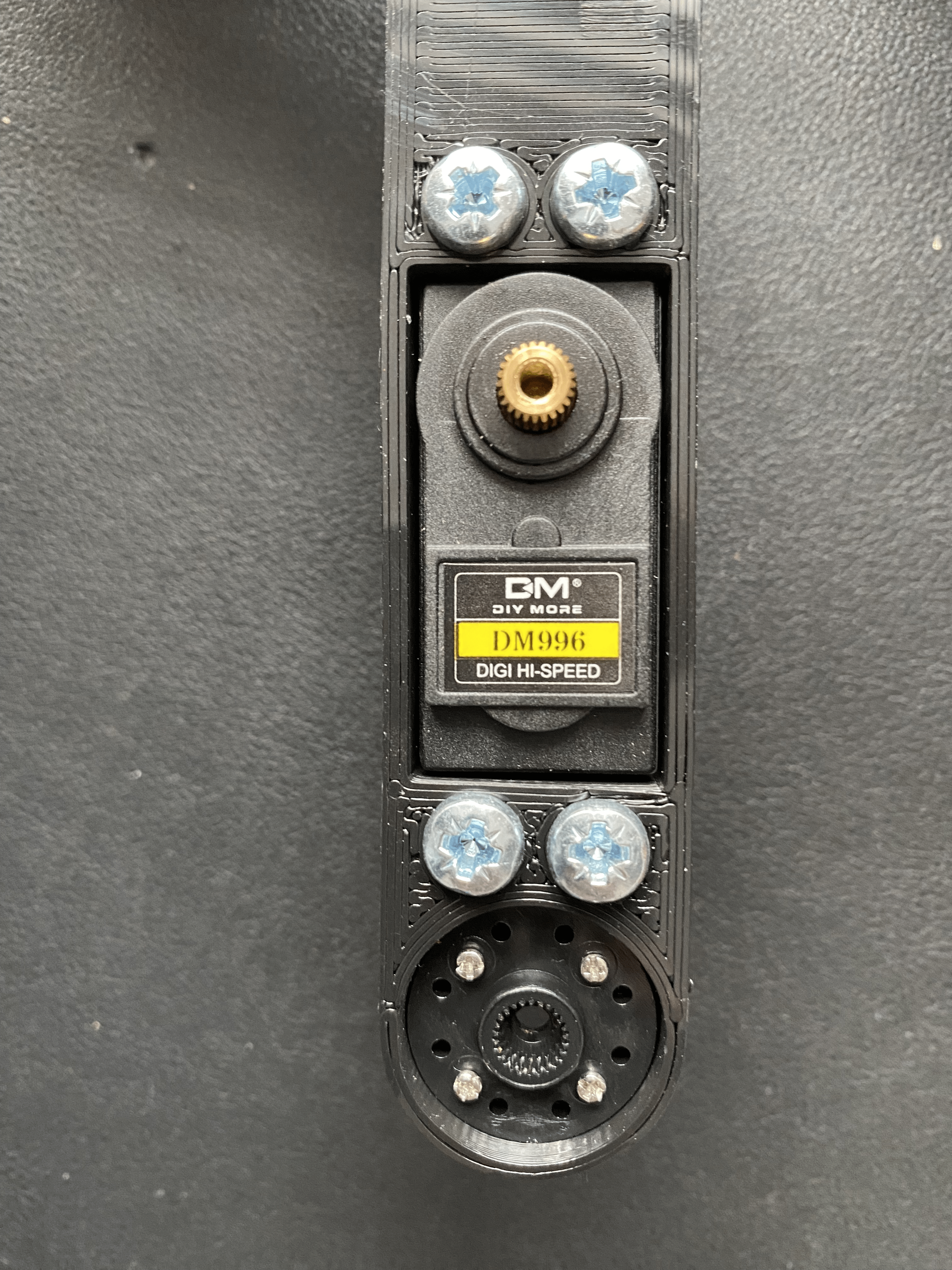
First, take the top part of the leg and attach the servo in the hole. The gear of the servo should be facing the same way as the hole at the top for the circular servo attachment. Then attach the circular servo horn in the top hole using 4 small screws. After doing those 2 steps, it should look something like this.
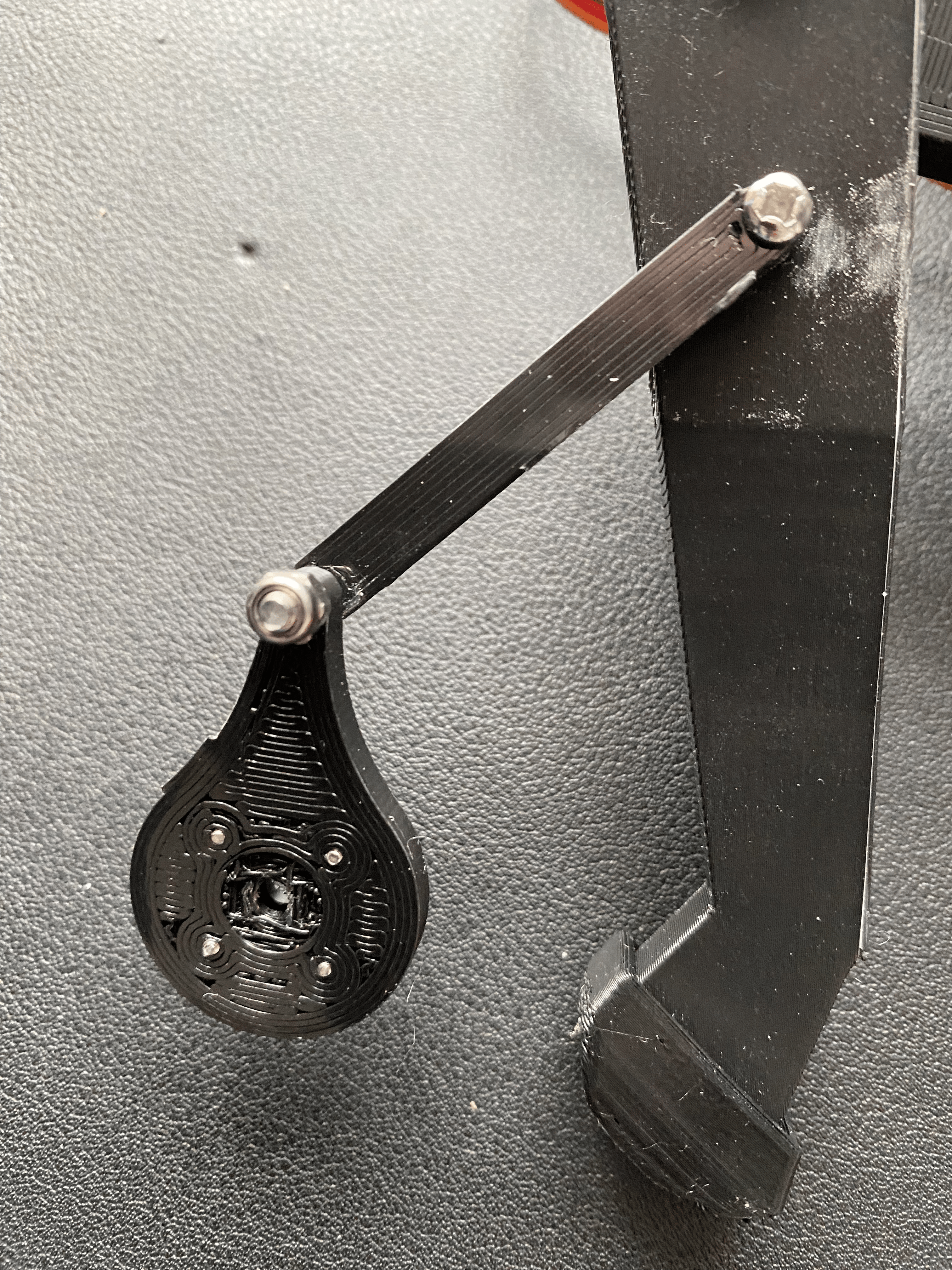
Then attach the Leg-Joint-Top and Leg-Joint-Bottom part together using an M3 screw and a locknut. Don't overtighten it, it should be able to rotate freely. Then attach it to the bottom leg part, after doing that it should look something like this.
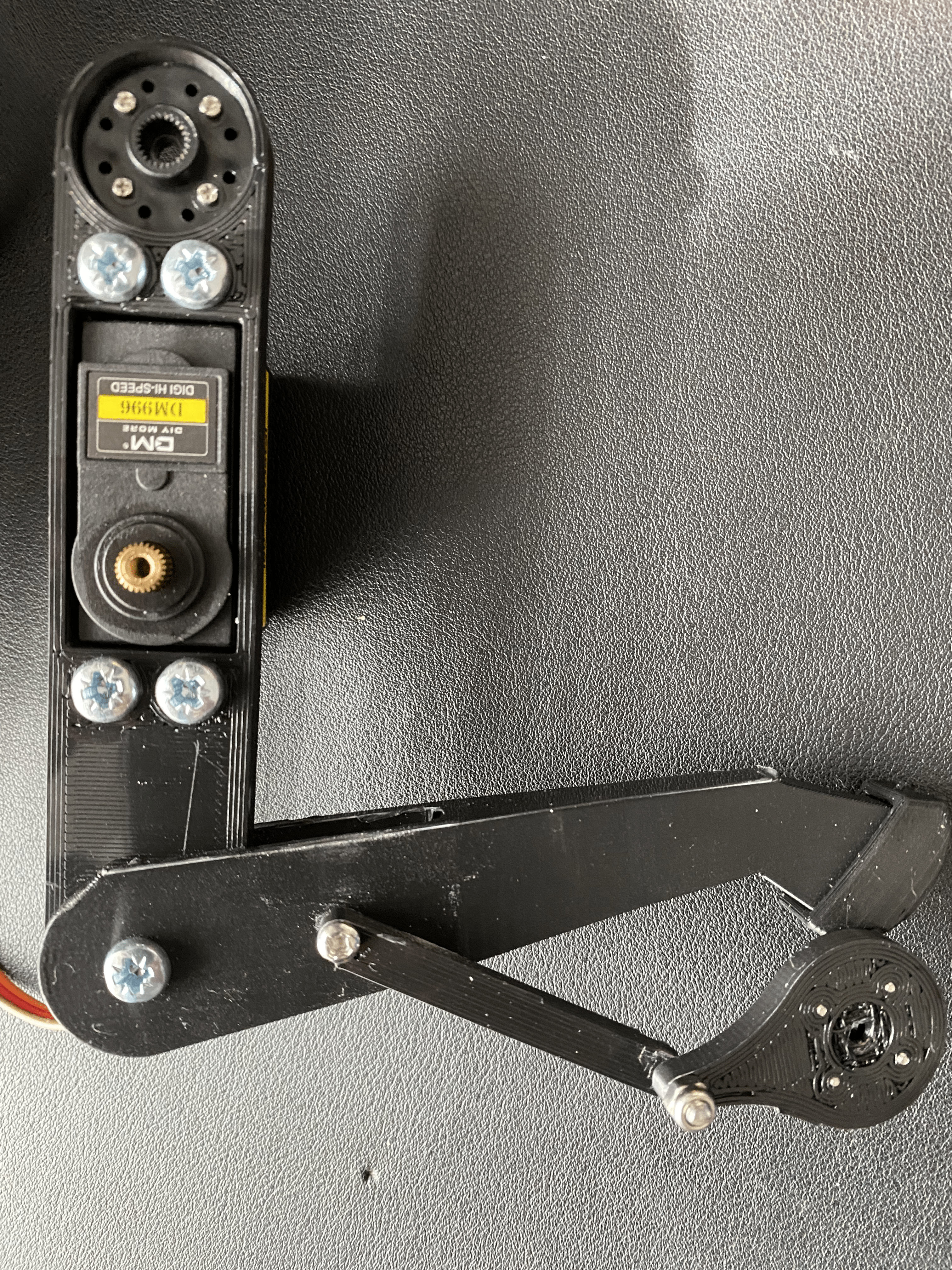
Then connect the top and bottom of the leg together using an M4 screw and a locknut, again don't overtighten it since it should be able to rotate freely. After doing that you should have something like this.
Then finally you must set the servo to 90 degrees, to do this connect the servo to the servo driver and run the following command on the Raspberry Pi.
$ python3 ~/AQLARP/scripts/set90.py
Then connect the top joint part to the servo, try to make the angle as close to 90° as possible. Then lock them together using an M3 screw.
And that is a completed leg. The rest of the servos will be added when assembling the body since if you attach them now, you won't be able to access some parts that you will need to access later.
Building The Main Body
In this chapter we will go over building the main body.
Required 3D-printed parts
- Main-Body
- Front-Back-Body x2
- Top-Joint-Left x2
- Top-Joint-Right x2
- Top-Cover
- Nut-Tool (Needed for assembly, breaks quite easily, you might need multiple)
Assembly
First install the 3D-printing inserts into the main body. There are holes for 6 M4 inserts at the top and 14 standoffs with place for M3 inserts in the bottom. To insert an insert carefully place it on the hole and then push it in using a soldering iron. This melts the plastic around it so the insert can slide right in and stay there securely.
Then install the 4 servos in the corners of the main body. These should be installed with the servo gear at the bottom. The locknuts should be on the inside and the screws on the outside. Unfortunately, it is practically impossible to reach the nuts at the bottom when tightening the screws. To address this you can use the nut tool file I provided. Load 2 nuts in it and place it where you need it and then screw the screws into the nuts and tighten the servo that way. Be careful not to overtighten it since the nut tool snaps very easily.
After that is done, you need to install the circular servo attachments to the top joint parts using the 4 small screws. Now connect the servos in the corners to the servo driver and set them to 90° using this command.
$ python3 ~/AQLARP/scripts/set90.py
Now install the top joint part, make it so it is as straight as possible. Then use an M3 screw to screw it into the servo from the side.
After this is done you can install the final servo into the top joint part using M4 screws and locknuts. Then set them all to 90 degrees using the command above again and install the leg on it, again trying to make it as straight as possible.
Now we will install the front and back cover. To do this first feed the wires of the servos through the hole at the bottom and into the main body, and then attach the front/back cover using 4 M4 screws and locknuts.
Wiring
We will create the wiring outside of the body before moving it in. This is easier since we have more space to work with outside of the body.
Connect the battery to the voltage regulators so you can configure their target voltage. Adjust the 20A voltage regulator until it outputs about 6.8V and adjust the XL4005 voltage regulator until it outputs 5V. This is very important as a wrong voltage could destroy your components.
Now wire everything up as shown in the image below.
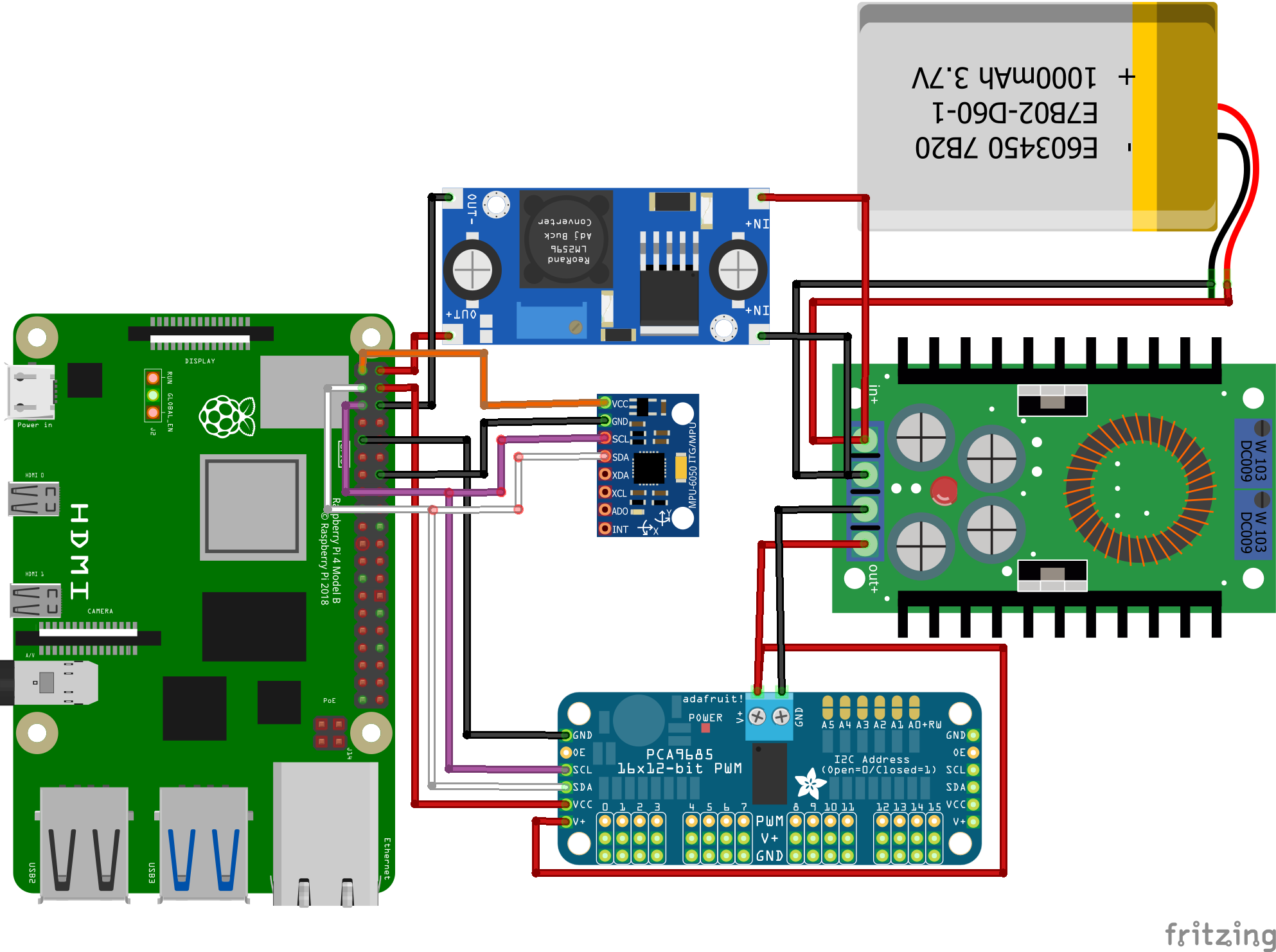
Please note the voltage regulators in the image aren't the same as those actually used. Make sure you connect the negative and positive pole correctly.
To connect the gyro and servo controller to the same pin you need Y-wires. You can easily create 2 of these by cutting open 2 jumper wires and soldering 3 parts together.
Connecting the servos
It is vital you connect each leg to the correct pin on the servo controller. The top joint should be the first of the 3 pins, the bottom joint the second and the sideways joint the third. The pins for the legs are as follows:
- Front Left: pin 9-11
- Front Right: pin 0-2
- Back Left: pin 6-8
- Back Right: pin 3-5
Installing in body
Now you just have to install all components in the body as is shown in the image below.
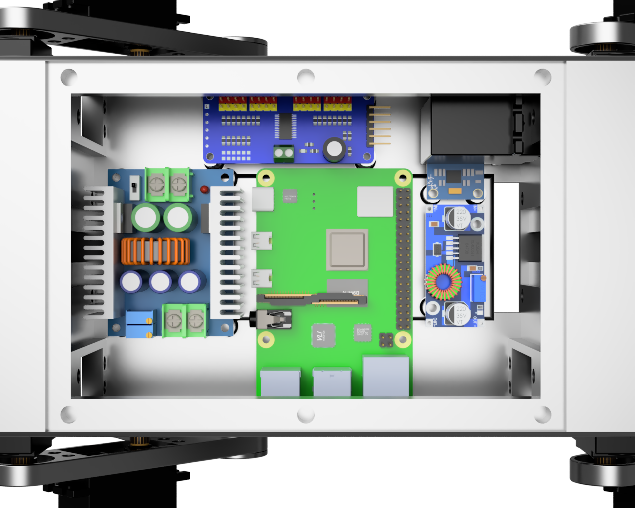
After that is done you just have to install the top cover and then you're done!
Installing software
In this chapter we will go over installing and setting up all software required for AQLARP to work. You should already have AQLARP's GitHub repo cloned in your home directory as specified in chapter 4.1
Installing ros2
AQLARP is built using ros2 iron, it might work with later versions but this is untested. To install ros2 iron you can follow their installation instructions. After installing ros2 you must also install colcon, which is ros2's build system. To do this run the command below.
$ sudo apt install python3-colcon-common-extensions
Sourcing ros2 automatically
To use ros2 you must source it every time, which can be annoying. To do this automatically run the following command.
nano ~/.bashrc
Then add these 2 lines at the end of the file.
source /opt/ros/iron/setup.bash
source ~/new_ws/install/setup.bash
Then press Ctrl + O to save and Ctrl + X to exit. To make this apply you should log out of the Raspberry Pi and start a new shell session.
Installing dependencies
To install dependencies first go into the workspace directory. To do this run the following command.
$ cd ~/AQLARP/ros2_ws
Then run the following command to install all required dependencies using rosdep.
$ rosdep install --from-paths src -y --ignore-src
Then additionally you have to install pygame using pip, since the version rosdep uses is severally outdated. To do this run the following command.
$ python3 -m pip install pygame
Building the code
You should be in the workspace directory as specified in the previous step. Then to build the code run the following command and wait for it to complete
$ colcon build
Calibrating the servos
Since the servos aren't exactly at 90° they have to be calibrated. To run the calibration script run the following command.
$ ros2 run aqlarp_motors calibration
Then to use the calibration script use the left and right arrow keys to increase or decrease the angle offset and use the up and down arrow keys to switch servo. You should try to set all servos as close to 90 degrees as possible.
Running the code
To run all code of AQLARP, and thus start the robot, run the following command.
$ ros2 launch aqlarp_main aqlarp.launch.py
To control the robot you will have to connect a ps4 controller. You can either do this by using a cable and connecting it using one of the USB ports, or alternatively you can use the instructions in the next part to connect the ps4 controller wirelessly.
The controls for AQLARP are as follows:
- Playstation button: start and stop the servos
- Left Joystick: Make the robot strafe in the direction you specify
- Right Joystick: Make the robot turn by moving the joystick left and right.
Connecting ps4 controller wirelessly
Open a command prompt on the raspberry pi (with ssh) and run the following command to get into the Bluetooth command line.
$ bluetoothctl
Then start scanning for Bluetooth devices with the following command.
scan on
Now press and hold the PlayStation and share button on your controller for a few seconds until the lightbar starts flashing. Then look at the output in your terminal for something like this.
Device A4:AE:11:41:FD:98 Wireless Controller
Copy the MAC address (the numbers in the center) and run the next command to pair with the controller. Make sure the lightbar is still flashing, if it isn't flashing anymore hold down the PlayStation and share button again.
pair <MAC address>
Then finally to make it so the controller can connect to AQLARP by just pressing the PlayStation button, run
trust <MAC address>
Now type exit to exit the Bluetooth terminal. If you want to disconnect the controller, hold down the PlayStation button for 10 seconds. To reconnect the controller, press the PlayStation button once.
Making the code run on startup
If you want to make AQLARP's code run on startup so you can just connect the controller and use it, you will have to create a file called aqlarp.service at /etc/systemd/system/.
To do this run the following command.
$ sudo nano /etc/systemd/system/aqlarp.service
Then paste the following content into it.
[Unit]
Description="AQLARP daemon"

[Service]
User=AQLARP
Restart=always
RestartSec=1

Environment="LD_LIBRARY_PATH=/home/AQLARP/AQLARP/ros2_ws/install/aqlarp_interfaces/lib:/opt/ros/iron/lib/aarch64-linux-gnu:/opt/ros/iron/lib"
Environment="PYTHONPATH=/home/AQLARP/AQLARP/ros2_ws/install/aqlarp_sensors/lib/python3.10/site-packages:/home/AQLARP/AQLARP/ros2_ws/install/aqlarp_motors/lib/python3.10/site-packages:/home/AQLARP/AQLARP/ros2_ws/install/aqlarp_main/lib/python3.10/site-packages:/home/AQLARP/AQLARP/ros2_ws/install/aqlarp_interfaces/lib/python3.10/site-packages:/home/AQLARP/AQLARP/ros2_ws/install/aqlarp_input/lib/python3.10/site-packages:/opt/ros/iron/lib/python3.10/site-packages"
Environment="AMENT_PREFIX_PATH=/home/AQLARP/AQLARP/ros2_ws/install/aqlarp_sensors:/home/AQLARP/AQLARP/ros2_ws/install/aqlarp_motors:/home/AQLARP/AQLARP/ros2_ws/install/aqlarp_main:/home/AQLARP/AQLARP/ros2_ws/install/aqlarp_interfaces:/home/AQLARP/AQLARP/ros2_ws/install/aqlarp_input:/opt/ros/iron"

ExecStart=/opt/ros/iron/bin/ros2 launch aqlarp_main aqlarp.launch.py

[Install]
WantedBy=multi-user.target
If you use a different user than AQLARP or have cloned the GitHub repo in a different location, you will have to edit this file accordingly. To save the file press Ctrl + O and then press Ctrl + X to save.
Then finally to enable the service, run the following command.
$ sudo systemctl enable --now aqlarp.service
Ros2 Topics
This chapter outlines the various ros2 topics AQLARP has that you can interact with to adapt the robot to your use case.
Heading topic
Topic name: heading
Package: aqlarp_main
Description: with this topic you can specify where the robot should go to and at what speed. The heading parameters will be limited to a circle of radius one and the rotation parameter will be limited between -1 and 1.
Data type: Heading
Values:
float32 x_headingfloat32 z_headingfloat32 rotation
Power topic
Topic name: power
Package: aqlarp_main
Description: with this topic you can set the power to the servos on or off.
Data type: Boolean
Gyro topic
Topic name: gryo_angles
Package: aqlarp_sensors
Description: all gyro related data is published on this topic, this is published 100 times per second.
Data type: GyroAngles
Values:
float32 pitchfloat32 rollfloat32[3] angular_velocityfloat32[3] acceleration
Joint angles topic
Topic name: joint_angles
Package: aqlarp_motors
Description: with this topic you can specify the angles that all servos should be set to.
Data type: JointAngles
Values:
float32[12] angles
Disable joints topic
Topic name: disable_joints
Package: aqlarp_motors
Description: power off all servos
Data type: Empty
Inverse Kinematics
In this chapter we will look at the calculations behind the inverse kinematics of AQLARP. These calculations are based on trigonometry since it is quite easy to split all these problems into triangles. If you are not familiar with this topic or want more info, I would recommend watching the video below as it does a great job explaining this concept in a simple manner.
Inverse kinematics of the legs
In this chapter we will go over the inverse kinematic calculations for an individual leg.
Definitions
\(l_{1}\) Length of the femur (top part of leg)
\(l_{2}\) Length of the tibia (bottom part of leg)
\(x\) Desired x position of the leg
\(y\) Desired y position of the leg
\(z\) Desired z position of the leg
\(A\) Angle of the femur joint
\(B\) Angle of the tibia joint
\(C\) Angle of the sideways joint
Y-position calculation
The following calculation calculates the angle of the femur joint for a given y-position \(y\): $$A =\arccos\left(\frac{y^2+l_{1}^2-l_{2}^2}{2yl_{1}}\right)$$ The following calculation calculates the angle of the tibia joint for a given y-position \(y\): $$B =\arccos\left(\frac{l_{1}^2+l_{2}^2-y^2}{2l_{1}l_{2}}\right)$$
X-position calculation
The following calculation calculates the angle of the femur joint for a given x-position \(x\) and given a y-position \(y\): $$A = \arctan\left( \frac{x}{y} \right)$$
Z-position calculation
The following calculation calculates the angle of the sideways joint for a given y-position \(y\) and a given z-position \(z\): $$C = \arctan\left( \frac{z}{y} \right)$$
Combing Calculations
To combine these calculations we first do the X-position and Z-position calculation. $$A_{x} = \arctan\left( \frac{x}{y} \right)$$ $$C_{z} = \arctan\left( \frac{z}{y} \right)$$ First, since our rotation joint is moved inwards in relation to the leg, we must adjust the height to take the height the rotation joint is creating into account. We can do this as follows: $$y = y \pm \sin(A_{z}) \times 3$$ Then we must adjust our y value to take into account that we will have to extend our leg further if we want to remain at the same height but go further forward or to the side. This is done as follows: $$y = \frac{y}{\cos(A_{x}) \times \cos(C_{z})}$$ Then we can do our Y-position calculations with this adjusted \(y\) value. $$A_{y} =\arccos\left(\frac{y^2+l_{1}^2-l_{2}^2}{2yl_{1}}\right)$$ $$B_{y} =\arccos\left(\frac{l_{1}^2+l_{2}^2-y^2}{2l_{1}l_{2}}\right)$$ Then finally we can combine them by adding them together. $$A = A_{x} + A_{y}$$ $$B = B_{y}$$ $$C = C_{y} + C_{z}$$
Code
After transforming all these calculations into code, we get this:
def calc_angles(leg, x, y, z):
    # Calculate top joint position to reach X coordinate
    x_pos_a = atan(-x / y)
    # Calculate side joint position to reach Z coordinate
    z_pos_c = atan(z / y)
    # Adjust the target height because of the Z-joint having 3cm offset until the leg
    if leg == 0 or leg == 3:
        y += sin(z_pos_c) * 3
    else:
        y -= sin(z_pos_c) * 3
    # Adjust the target height for the X and Z offsets
    y = y / (cos(x_pos_a) * cos(z_pos_c))
    # Calculate top joint position to reach Y coordinate
    y_pos_a = acos((y * y + leg_length1 * leg_length1 - leg_length2 * leg_length2) / (2 * y * leg_length1))
    # Calculate bottom joint position to reach Y coordinate
    y_pos_b = acos((leg_length1 * leg_length1 + leg_length2 * leg_length2 - y * y) / (2 * leg_length1 * leg_length2))
    # Merge all angles and convert them from radians to degrees
    A = degrees(x_pos_a + y_pos_a)
    B = degrees(y_pos_b)
    C = degrees(z_pos_c)
    # Adjust the angles for the servo orientation and return the result
    return (
        (90 - A) if leg == 0 or leg == 3 else (90 + A),
        B if leg == 0 or leg == 3 else (180 - B),
        (90 + C) if leg < 2 else (90 - C)
    )
Inverse kinematic of the body
The inverse kinematics of the body is to transform pitch, roll and rotation into offsets for the x, y and z coordinate of a leg.
Definitions
\(l\) length of the body
\(w\) width of the body
\(pitch\) desired pitch
\(roll\) desired roll
\(rotation\) desired rotation
\(rotation\) desired rotation
\(m_{x}\) leg movement x
\(m_{y}\) leg movement y
\(m_{z}\) leg movement z
\(x\) x position of a leg relative to the center
\(z\) z position of a leg relative to the center
Pitch
The calculations for pitch are as follows: $$m_{x} = \frac{l(1-\cos(pitch))}{2}$$ $$m_{y} = \frac{l\sin(pitch)}{2}$$
Roll
The calculations for roll are as follows: $$m_{z} = \frac{w(1-\cos(roll))}{2}$$ $$m_{y} = \frac{w\sin(roll)}{2}$$
Rotation
The calculations for rotation are based on a rotation matrix. These calculations are as follows:
$$m_{x} = (x \times \cos(rotation) - z \times \sin(rotation)) - x$$ $$m_{z} = (x \times \sin(rotation) + z \times \cos(rotation)) - z$$
Combining Calculations
To combine these calculations you just calculate each one separately and then calculate the sum of all x calculations, then the sum of all y calculations and finally the sum of all z calculations.
Code
After transforming these calculations into code, we get this:
def calc_leg_offsets(leg, pitch, roll, rotation):
    # Get the X and Z coordinate of the leg
    x = (body_length / 2) if leg < 2 else -(body_length / 2)
    z = -(body_width / 2) if leg == 0 or leg == 3 else (body_width / 2)
    # Calculate the height difference of the leg to reach the target pitch
    height_diff_pitch = x * sin(radians(pitch))
    # Calculate the height difference of the leg to reach the target roll
    height_diff_roll = z * sin(radians(roll))
    # Calculate the X and Z offsets to keep the body centered
    movement_x_pitch = x * (1 - cos(radians(pitch)))
    movement_z_roll = z * (1 - cos(radians(roll)))
    # Calculate the rotation offsets
    movement_x_rotation = (x * cos(radians(rotation)) - z * sin(radians(rotation))) - x
    movement_z_rotation = (x * sin(radians(rotation)) + z * cos(radians(rotation))) - z
    # Merge the offsets and return them
    return (
        movement_x_pitch + movement_x_rotation,
        height_diff_pitch - height_diff_roll,
        movement_z_roll + movement_z_rotation
    )